


Motor > Revision
Preparation

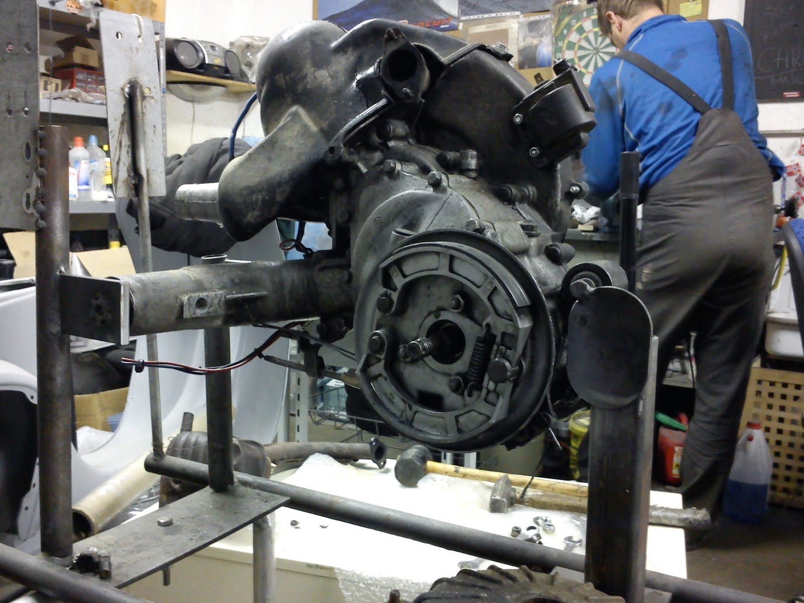
Remove Engine
Check Out Engine Removal
Jack Up Engine
It would be a great advantage and help if you own a motor stand or if your are in the position to build yourself one. But you will be able to conduct all described without as well.
Transmission Oil

Drain Transmission
First of all drain the transmission in order to avoid any 'oily' surprises later on such as when removing the break anchor plate or splitting the engine case. Place a suitable container underneath the oil drain plug and open it (wrench size 11). Give it some time until all oil has ran out.
Attachment Parts

Remove Attachment Parts
Now remove the (plastic) engine cover, the flywheel cover and the exhaust manifold.
Flywheel


Removing Flywheel
Removing the flywheel can be one of the most difficult and time consuming jobs during the engine revision process. Unscrew the nut in the center (wrench size 14). You need to prevent the flywheel from moving by either using a flywheel holding tool or jaming one of the fins against a screwdriver which you stick into one of the holes holding the flywheel cover screws. Alternatively and the best solution use an impact driver. Apparently there is several options to force the flywheel up the shaft:
- Flywheel Puller
- Push against the circlip
- Gear Puller
- Hammer, Screwdriver and Patience
The most elegant, easiest and actually rather less expensive way is to use a flywheel puller. Unfortunatly not all V50 flywheels are equipped with the inside threads needed for the use of this special tool. On some smallframes there is a circlip which should be left in place. Unscrewing the nut will push it against the circlip and the flywheel will be forced up the shaft. If your flywheel has neither of those two options you have to unscrew the center nut, attach the gear puller and tighten it. But be careful to not overdo it! The flywheel is made of aluminium and there is a risk to break off one of the fins or to chip some material at the edge. Tighthen the gear puller screw strongly until you feel there is pressure on the shaft. Some hammer taps on the gear puller screw may well be necessary to loosen the flywheel and make it pop off the shaft. Make sure that the woodruff key from the shaft is not lost.
Stator


Removing Stator
Open the little black plastic box that stores the cable connectors. Open all connections but take some notes of which colors were connected. In case of an inbuilt ignition coil, remove the spark plug connector. Set an aligned mark that goes from the stator to the engine case in order to identify the position for the ignition timing. In case that the ignition was set wrongly you still set a mark but after reassambly you have to adjust the timing accordingly. This is described in the respective chapter about iginition timing, Adjust Ignition. Open the screws that lock the stator and remove the stator and pull out the whole set of cables.
Brake Anchor Plate


Remove Rear Brake Anchor Plate
Undo the 3 screws (wrench size 13) and pull off the anchor plate from the engine housing. Not would be the time that you remember that you have forgotten to drain the transmission.
Cylinder
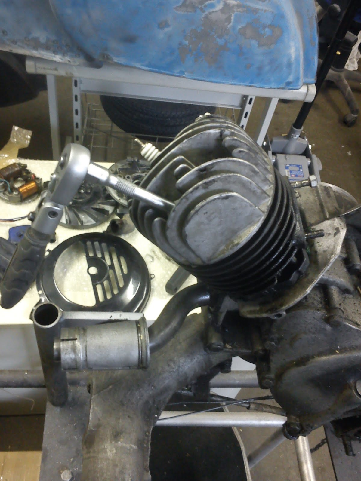

Take Off Cylinder
Undo the spark plug (wrench size 21). Undo all 4 cylinder head screws (wrench size 11). It is easier to remove the cylinder head now whilst the cylinder ist still attached. Now undo the 4 screws that lock the cylinder to the housing (wrench size 11). Carefully pull off the cylinder from the 4 bolts and the piston.
Piston


Remove Piston
Remove one of the two circlips that hold the wrist pin in place. Press out the wrist pin using an appropriate tool such as a drift punch. The wrist pin either runs in a needle bearing or in a bearing shell. If you find any damage on either of both, replace it with a new item. It is enough to press out the wrist pin far enough until it has left the connecting-rod top end. Now take off the piston together with the wrist pin.
Intake Manifold

Remove Intake Manifold
Undo the 2 nuts (wrench size 10) from the stud bolts. Remove the intake manifold together with the attached sleeve. By the way, the V50 usually has got two stud bolts whereas the PK50 is equipped with 3 of them.
Ignition Coil

Remove Ignition Coil
In the original setup there are 2 nuts (wrench size 8) that sit on two screws that go through the housing and the retaining plate. Undo both and remove the igintion coil and plate.
Clutch


Remove Clutch
Remove all 6 screws (wrench size 10) that hold the coupling cover. Take off the cover. Use a small screw driver to carefully pull out the spring clamp from the wider hole of the clutch plate and lock it with its end inside the hole. Bend back the locking part of the washer in order to be able to turn and open the center nut (wrench size 17). This is done best with a small screw driver followed by a drift punch. Either you use a special tool to lock the coupling cage and open the center nut with a no. 19 wrench or you don't lock the coupling cage and use an impact driver. The thread is an ordinary one which opens counterclockwise. Use a clutch puller in order to get the clutch off the gear shaft. Only in very rare cases you may be able to unlock the clutch from the coupling cage using a screw driver. It is therefor definetely recommended to get the special tool (clutch puller). Thread in the clutch puller into the clutch and tighten the center screw of the tool. This will force the clutch to come off the gear shaft. Now remove the clutch out from the coupling cage. Might become a bit of a fiddeling work but it is possible. Pay attention to not loose the woodruff key that sits on the gear shaft!
Primary Drive


Remove Primary Drive Sprocket
Bend back the locker of the washer. Undo the nut (wrench size 19). Use an impact driver to avoid using a special tool to prevent the crank from rotating. Do NOT 'abuse' the connecting-rod top end to do so! In the event that you decided to keep the piston attached: be aware that using an impact driver will make the crank rotate and by that make the piston move. If you want to reuse the old piston, make sure you buffer it with some soft towel or similar against the engine housing. You only need to trigger the impact driver shortly to loosen the nut.
Again pay attention to not lose the woodruff key. Secure an upward position before removing the sprocket. The sprocket can only be removed if the coupling cage is turned into the position that the big notch is in line with the sprocket (see pic). Otherwise the coupling cage its metal edge will prevent you from moving out the sprocket.
Engine Case


Split Engine Case
Undo ALL nuts (wrench size 11) of the engine case. Make sure none is forgotten and left, especially around the area where the stator gets mounted. Carefully push one half away from the other by giving some smooth blows using a rubber hammer. Watch out and remember that the engine case is made of aluminium which can break much easier than compared to steel. DO NOT USE A SCREWDRIVER TO LEVER! You may damage the seal face. There is one small spot at the rear bottom side of the engine (next to the aligning bolt) where you may carefully lever.
Now you look at the engine's inside.
Kickstart

Remove Kickstart Sprocket
Unclamp the big spring. No worry, not a lot of tension on this one, it won't jump in your face. Remove the output shaft and the respective sprocket behind. Pay attention to the spring (softly loaded) and the washer that sits between the sprocket and the output shaft bearing. Now rotate the kickstart and pull to fully remove it.
Drive Shaft


Remove Drive Shaft
The best way to remove the drive shaft is to either use a steel hammer and some chunk of wood or preferably a rubber hammer. In any case, always protect the end of the shaft from getting deformed by the hammer beats. Beat on the end of the shaft to push it out from the drive shaft bearing. Normally the shaft should just pop out as soon as it has left the bearing. There is only limited space but again the shaft should more or less automatically slide out of the shift-fork after it has left the bearing. Just be careful and hold the end of the drive shaft where the gear wheels are located to not let it fall down when the whole piece starts popping out. Leave the gear wheels on the shaft but only remove them if really necessary. Like e.g. in case you want to change the transmission ratio. If you feel that your transmission performance is sort of a wobbly one you may decide to replace the gear selector and its respective parts such as springs and balls. But beware of the balls which may jump out and either hurt you or at least get lost in some dark corner of the workshop. It is also not the easiest task to get the new parts back in and lock the gear selector and all of its parts back into the right position.
Coupling Cage

Remove Coupling Cage
In principle it shouldn't be difficult to remove the coupling cage. Especially when the drive shaft has been removed before. All you have to do is to remove the circlip located on the shaft side of the cage and rotate the coupling cage until you can take it out from the engine half. There is one notch which is a bit bigger than the others. This one should be the one that lets you move out the cage on the bottom side where space is rather limited.
Crankshaft Seal Ring

Remove Seal Ring
Use an appropriate tool such as a screw driver to remove the crank shaft seal ring !Attention! Do not damage the seal face!
Bearings


Remove Bearings
All circlips must be removed prior to any bearing removal! As a next step make sure you understand from which side the respective bearing is inserted. Logically you have to drive them out from the opposite side. Always keep in mind when using some force that the engine housing is made of aluminium and therefore subject to easy damage such as cracks which are irrepairable or at least damn hard to fix. There are specific drift punch sets available that are worth the investment! If no special tool at hand and if necessary you may also use a socket of the right size. No need for a dedicated care to the bearings when driving out. You will bin them anyway.
The Engine Case


Engine Case
Now most parts have been removed and the two engine case halves only contain the smaller bearings and the crank shaft (usually on the alternator side).
Components

Components
Here is another overview of all removed components.
Crank Shaft


Drive Out Crank Shaft
In order to drive out the crank shaft that still sticks inside the engine case it is highly recommended to always use some chunk of wood that is placed between the crank shaft end and the hammer. Otherwise you will most likely damage thread of the crank shaft. Most often the crank shaft requires some sharp force in order to come loose. In addition the bearing usually keeps sticking to the crank shaft, too.
Engine Case Cleaning


Engine Case Cleaning
A rather time consuming and painstaking task. All little helpers are welcome and appreciated; be it cleanser, be it compressed air, be it thinner etc pp. Remember that you have to get rid of about 30 year old dirt. We recommend a screw driver to remove the biggest chunk of dirt first. Now a wire brush will help to remove the remaining stuff that the screw driver couldn't take care of. Now we take it to the part washer to remove most of the oily and greasy particles. Repeat those steps until all dirt is gone. Please do not wire brush, neither manually nor by machine, any of the seal faces! The final state of course very much depends on your personal needs and desires. We often close all open areas and basically seal the inside from the outside and sandblast the outside of the engine case halves. You may leave the 'natural' surface of the cleaned aluminium or give it a final nice look by adding some aluminium paint (see end of this thread). We use a paint that is heat resistent, that doesn't require any primer, that is resistent against oil and petrol and last but for sure most important doesn't rub off like many rim silver sprays do.
Shift Linkage


Remove Shift Linkage
"Never change a running system"! Meaning as long as the socket play seems to be ok and no oil is leaking out we usually see no need to touch the shift linkage set. In our particular case the system had some exceeding play and we were actually concerned about leakage and the proper mechanical functionality. Hence we consequently decided to remove the whole set to clean it and reniew the parts needed. Firstly undo the upper screw that locks the shift linkage (wrench size 14). The most difficult part can be (not a must and not always but quite often) to remove the little cone-shaped bolt that attaches the gear selector to the shaft. Us a hammer and a pin punch. Sometime you have to fiddle around with other tools in order to get that little pin out. Make sure you start at the right end of the pin! Again it is slightly cone-shaped.
As soon as the pin is out, you can lift off the gear selector from the shaft. Now turn the shift linkage carefully and remove it from the two slots. Be careful to not lose the washer!
Crankshaft-Simmering

Drive Out Crankshaft-Simmerring
Use the drift punch tool to remove the Crankshaft Simmering. Drive out the seal ring in the outward direction.
Reassembly


Paint Finish
Nothing vital but something everyone can decide individually. Some may feel that a proper cleaning is good enough. Then again such a paint finish gives the whole job the little extra as it is really looking like brand new. Of course you shouldn't just use any type of paint. The basic requirements should be resistence against petrol, oil, any kind of hydrocarbons as well as heat. Certainly we would want some paint that is abrasion resistent. We have found something suitable at "MW-Werkstatt-Produkte" - Aluminiumspray: heat resistent, acid resistent, oil resistent, abrasion resistent, scratch resistent, less expensive and the real advantage that it isn't actually looking like painted but just like brand new aluminium.
Close all open ports and seal the inside from the paint. Use a proper tape that can easily be removed again without leaving glue on the seal faces. Now spray and dry.
Shift Linkage


Shift Linkage Assembly
Firstly replace any worn out O-rings that sit on the shaft of the shift linkage. Carefully insert the shift linkage and softly turn in the screw (wrench size 14) that locks the shift linkage in position. Now put back on the gear selector (watch out for the correct position), insert the little pin from the right side (remember it is slightly cone-shaped). Finally fully tighten the screw (wrench size 14) that holds the shift linkage.
Kickstart Rubbers


Insert Kickstart Rubbers
Most of the time the two kickstart rubbers inside the engine case are either heavily worn out or completely missing (you will find the old rubber parts somewhere inside the gearbox). Simply lever out the old ones and push in the new ones. It will ease the job if you add some grease to the rubber. Make sure you check out the correct position of each rubber before you insert them.
Whilst having access to all wearing parts, inspect the o-ring that seals up the kickstart shaft. We recommend to always replace it as soon as the whole kickstart part has been removed.
Left Side Bearings


Tap In Bearings
Preferably use a special drift punch set in order to tap in the engine bearings. Alternatively you may use a steel socket but make sure you have the correct size! Always and only use the outside ring of the bearing, never the inner cage ring!
Tap them in carefully and with controlled force. We recommend to heat up the engine housing prior to that. By heating up the aluminium the bearing shell gets wider and the bearing will almost automatically slide inside.
Important though is to secure that the bearing slides inside in an absolutely straight position. !AGAIN: NEVER EVER BASH ON THE INNER BEAERING RING! THERE IS A GREAT CHANCE TO SCREW UP THE BEARING IF DOING SO!
The drive shaft bearing is tapped in from the outside. There is no circlip holding this one. Just like all original bearings it is an open version. However in order to support the original gasket on the brake anchor plate you may use a half side closed bearing. The closed side points towards the outside/anchor plate. (Instruction how to prepare the bearings you find under the bearings and simmerrings section. Simply unclamp the ring on the required side by using a small screw driver and reomve the grease inside the bearing.).
The bearing for the coupling is inserted from the clutch side. This one has got a circlip.
The crankshaft bearing on the left side is tapped in from the inside. This one also has got a circlip.
Please pay attention to the different size of the two crankshaft bearings. The outside diameter is the same but the inside diameter differs! In case of doubt, take the new bearing and move it over the shaft of the crankshaft to check if it fits the shaft diameter.
Again, do NOT forget to set all circlips as described above! You may now already insert the crankshaft seal ring. If you forget this one, you must reopen the engine again as it would let transmission oil intrude into the combustion chamber. Same as for the bearings goes for the seal rings: use a proper tool, preferably a drift punch. Only work on the outside of the simmerring, never on the inner ring. The 'open' side of the simmerring points towards the crank case.
Right Side Bearings


Right Side Bearings
Same procedure as on the left side, apart from the fact that you should place this side flat on a surface. It makes sense to cushion the engine case.in order to avoid any damage to the housing as well as to the seal faces. You may again heat up the bearing shells to ease the process of insertion. If you 'cold-press' the bearings we recommend to add some grease to the bearings and shells. Again, make sure that the bearing is tapped in absolutely straight. Use the respective drift punch or socket in order to tap in the bearings. As always: only put pressure on the outside ring of the bearings. Never on the inside!
Now comes the corresponding seal ring (simmerring). Flip over the engine case, grease the seal ring and tap it in properly ('open side' pointing towards the inside). Sometimes it is even enough to use the power of your fingers to push it in. Caution: It may well be possible to insert the seal ring a little bit too far! Just make sure that the top of the seal ring is flush-mounted with the shell!
Coupling Cage


Install Coupling Cage
It is of paramount importance that you keep the right order when reinstalling all the parts. Otherwise you will run into problems that let you redo all that has been done from now on. The first part now is the coupling cage. Look out for the big notch (window). Having this one in the right position will allow you to easily slide in the coupling cage shaft into the bearing. Now use some chunk of wood and a 'real' hammer to drive in the coupling cage fully inside the bearing.
Kickstarter


Install Kickstarter
Push the kickstart sprocket wheel on the shaft of the coupling cage. This has to be done prior to the drive shaft installation! Otherwise there would not be enough space to conduct this job. Insert the washer between the bearing and the spring. Now push the sprocket wheel on the shaft but watch out that the spring doesn't push back off the sprocket again. Now slide-in the kickstarter and make sure that the gearing matches. The kickstarter spring looks like a massive one but hasn't got much of a tension. You can actually insert it manually without much force.
Drive Shaft


Drive-in Drive Shaft
This part we haven't completely dismantled; the drive shaft + gear wheels and shifting claw. Sometimes the shifting claw is worn out but in this case we went without replacement. If you fully dismantle the drive shaft you will find a spring and two steel balls that lock the shifting claw to the wanted gear wheel. Reassembling the spring and balls can become a nightmare without the proper special tool. Removing the gear wheels instead isn't a big thing. Simply remove the circlip at the front of the gear wheel and take them off (not shown).
That's why we reinstall the complete drive shaft with all its components. Before you drive in the drive shaft you must lock the drive shaft bearing in order to avoid it from slipping out of its shell again. The easiest method is to use a couple of big washers to lock the bearing. Just put enough washers on each bolt, make sure that the washers are overlapping the bearing and lock them in position with three nuts.
Now comes again the chunk of wood that you have used already before and which you should keep handy for any kind of such work. Bash in the drive shaft but use controlled force. You have locked the bearing in position and all you have to do now is to drive in the drive shaft slowly but constantly until it has reached its final position. You can feel and hear it when the shaft is on the bearing; now you better stop, don't overdo it! As a reference of how far the shaft should be inside you can have a look at the pictures. As you can see, the inner gear wheel is slightly under the level of the housing edge and there must be some small gap left between the kickstarter and the gear wheel. If you would like to adjust it professionally, which doesn't mean that any of our engines didn't work, check out some of the bigger online shops for Vespas. They offer some special tool to measure the distance between the gear wheels.
Crank Shaft


Crank Shaft Assembly
Most often the right side bearing remains on the crank shaft during the removal process - tightly. Removing it can for sure be one hell of a job. There are certainly special tools out there for purchase, but most of us don't really have immediate access to them. So let's try finding another way of how to remove it. Try to find any kind of tool that can widen the gap between the crank cheek and the bearing. Something wedge-shaped would be most suitable. Now try to enlarge the mentioned gap until the bearing pops off.
Insert the crank shaft into the left bearing. Soft and easy avoiding any damage to the bearing. It either slides in automatically or you have to softly push it inside. Position the crank shaft in a way that the woodruff key sits on top and cannot fall off. You may need to fiddle with it or even softly push the woodruff key inside its slot. Attach the primary drive sprocket. NOTE: The woodruff key sets the sprocket's position onto the crankshaft. It secures that the sprocket stays in the right position relative to the crankshaft and doesn't spin on the shaft by mistake. It's important to note that the torque on the sprocket nut is what keeps it mounted securely to the crankshaft. Add the locking washer and the nut (wrench size 19). Lock the nut using an impact driver. Again, be careful that the crank shaft will be shortly turning, so you don't damage the piston rod or any other part of the engine. Cushion the area around the piston rod with some towels or anything that can prevent the piston rod from striking on the crank case. Bend the little lip of the washer to lock it properly.
Housing


Reattach Housing
Firstly insert the layshaft (aka christmas tree) into the right half of the housing (ignition side). Doing this will greatly help you when closing both parts of the housing. If you would insert the layshaft into the left housing there is a great chance that it gets jammed somewhere between housing and gear wheels. Now thoroughly clean all seal faces. You may use silicon remover or anything that completely vanishes oil and greasy substances. We recommend to use some heat resistant sealing compound in addition to the genuine paper gasket. We have made the best experience with this combination and we have never had any engine that was that properly sealed for long like compared to the described method.
After the application of selaing compound you should not wait for too long until you reattach both parts of the housing. The compound is going to get hard after a while, hence there is no time to waste. In order to make both halves attach easily you have to secure a couple of things. Very often they get jammed. While you push one half onto the other you should every now and again turn the drive shaft, move the kick starter and turn the crank shaft. That will support each shaft inside to smoothly slide into its targeted position. Do not apply too much force or you may face the risk of breaking the housing! You may use a rubber hammer to support the job of pushing one half onto the other. During the whole process, make sure that all parts but especially the crank shaft can be easily moved. You can also use some of the screws for the housing to avoid a slip-out on the sides. But do not use the screws to pull the cases together! Both halves must slip without brutal force. It is simply a matter of matching all inside parts into the right bearings and positions. Thats why you should continuously turn the shafts and the kickstarter. 'Listen' to your fingers and you will feel the moment when all fits perfectly well. The only moment when you might need some force is the moment when the bearing has to slide onto the crank shaft. As easy as the bearing could be pushed onto the one side of the crank shaft (the one where the sprocket sits) the harder it goes on the other side where the flywheel is located. Under perfect conditions you will hear/feel a soft 'plop' at the end when both halves finally came together. That is the perfect moment when you will know that it has been done. Now finally check again all moving parts for proper functionality. In case any of them does not turn smoothly, you have to separate the halves again and start from the beginning. Do NOT use any violent force to try make things moving! If they don't move you have made a mistake and you better disconnect the halves again before you break or damage anything.
Now that both halves are successfully reattached, you should tighten all screws properly before the sealing compound gets hard. This should be done criss-cross or at least in a way that the any pressure is evenly distributed.
Piston and Cylinder


Piston and Cylinder Reassembly
The first thing you do is to protect the crank case from anything falling inside. Especially the snap rings for the piston are subject to that. We usually stuff some old shirt into the case. Most often we decide to replace the original setup with the famous DR50. Insert the new stud bolts with the short thread facing towards the cylinder. This is done best by locking two nuts on the stud bolt. Now place both piston rings on the piston. Watch out that the notch on each piston ring is in the right position. Insert one of the snap rings inside the piston and induct the piston pin just far enough that the con rod can still be attached. Adding some grease to the pin will help quite a bit. Pay attention the the little arrow on top of the piston. This arrow has to point towards the exhaust outlet! A wrongly positioned piston will result in a more than unwilling to run engine. After the pin is through the con rod top end, fully push in the pin and close the open side on the piston with the second snap ring.
Now cut off the extruding gasket on both sides of the crank case where the cylinder will be inserted. Use a razor blade or a small cutter but don't damage the gasket. Now add some sealing compound to the seal faces and put on the paper gasket for the cylinder. Grease the piston for a better insert. Turn the piston rings into the right position and softly squeeze them together using you index finger and thumb which should hold the rings while sliding the cylinder above the piston and the rings. Use the two cut outs at the bottom of the cylinder for your fingers to hold the rings squeezed until they are fully slided inside the cylinder. Make sure the exhaust outlet points backwards. Push down the cylinder completely. Now add all 4 washers and nuts (wrench size 11) and tighten them criss-cross.
Cylinder Head


Mount Cylinder Head
The advantage of the DR50 is that you can continue using the genuine cylinder head from your old 50ccm engine. Add the head to the cylinder and insert the 4 bolts. Use wrench size 11 to softly tighten up the bolts. Do not overdo it. No need to use any gasket or sealing compound. You may now already screw in the spark plug.
Outlet Manifold

Fix the Outlet Manifold
Easy job: add the gasket and position the manifold correctly. Before you fully push down the manifold make sure that you connect all nuts (wrench size 10). One of them can only be added whilst the manifold isn't fully down on the stud bolt. Now tighten up the screws carefully but strong enough.
Clutch Reassembly


Clutch Reassembly
Renewing the clutch linings can be found here.
Position the slot for the woodruff key on the shaft by moving the kickstarter. The best position for the slot is facing upwards. Now move the coupling cage until you can easily insert the clutch. Secure that the woodruff key slots are properly aligned (shaft and clutch). Take out the clutch again and carefully insert the woodruff key. Use some grease to make it better stick to the shaft. Make sure that under no circumstances the woodruff key falls down inside the engine housing. Either you would need to search for it for hours with a magnet or worst case you would need to open the engine again! Now carefully insert the clutch and slide it over the woodruff key.
Add the locking washer and nut and manually turn the nut (wrench size 17). Now fully tighten up the nut using an impact driver. Bend the lip of the washer to finally lock it against incidential opening.
Insert clutch pressure plate: Use a small screw driver to carefully pull out the spring from the wider hole and lock it with its end inside the hole. Insert the clutch plate with the small hole side first and release the spring again which will hold the clutch plate at its targeted position.
Clean both seal faces of the clutch cover with e.g. silicon remover. Add some sealing compound to both parts and attach the paper gasket. Close the cover and tighten up all screws properly. Still be careful as the screws turn inside aluminium in which the threads can easily get damaged by too much force. There are 2 screws that are slightly longer which belong to the bottom of the cover.
Cable Adjustment


Cable Adjustment
Take off the nut and clean and lubricate the cable adjustment properly. The big adjustment bolt (wrenc size 13) goes to the break anchor plate. The two smaller ones (wrench size 8) host the shifting cables. Now mount the bracket which holds the clutch adjustment bolt as well as it bundles all cables. In order to do so you have to remove one of the engine housing screws (wrench size 11) again. Screw in all adjustment bolts full way. This will make the final adjustment much easier after all cables are connected.
Kickstarter


Mount Kickstarter
The kickstarter will only fit when correctly connected to the gearing. Fix the position by screwing in the kickstarter bolt (wrench size 14).
Break Anchor Plate


Mount Break Anchor Plate
Add some sealing compound to both seal faces and attach the paper gasket. Now put on the brake anchor plate, add the washers and tighten all 3 nuts (wrench size 13).
Intake Manifold


Mount Intake Manifold
Add sealing compound to the manifold seal face as well as to the engine side that connects to the manifold. Attach the paper gasket and mount the intake manifold. Tighten the 2 nuts (wrench size 10). Make sure that you carefully install this part and that it is properly sealed. This is the area which is most often leaky which is leaving some unpleasant staints of oil on your engine and even rear wheel.
Manifold Sleeve and Felt Washer


Manifold Sleeve and Felt Washer
Widen the steel ring just enough to move the sleeve over the manifold. Now release the steel ring and if necessary turn it until it locks the sleeve properly. The sleeve might feel wobbly but it must not slide off.
A part that is often not paid enough attention to and which is responsible for many engine trouble is the felt washer. That particular washer made of felt seals the carburetor from false air intake. There are newer variants which work with a small rubber o-ring inside the carb. Having such makes the use of the felt washer of course obsolete.
It is recommended to add some lubrication oil such as WD40 to the felt washer before it is inserted. Make sure the felt washer's diameter matches the intake manifold size.
Transmission Fluid


Fill in Transmission Fluid
Never forget filling in transmission fluid before you start up your engine again. Add a new gasket ring and close the drain plug (wrench size 11) carefully. Those threads are really weak ones and rather easy to destroy. Unscrew the oil filler screw (wrench size 11) (this one has been recut before and a wrench size 13 screw was used). Fill in SAE 30 transmission fluid. You have reached the correct fill level as soon as the fluid runs out again. That information is only valid as long as the engine is in the similar position like when it is built-in. As a rule of thumb this is round about 250ml. Add a new gasket and softly tighten the filler screw.
... to be continued
... to be continued